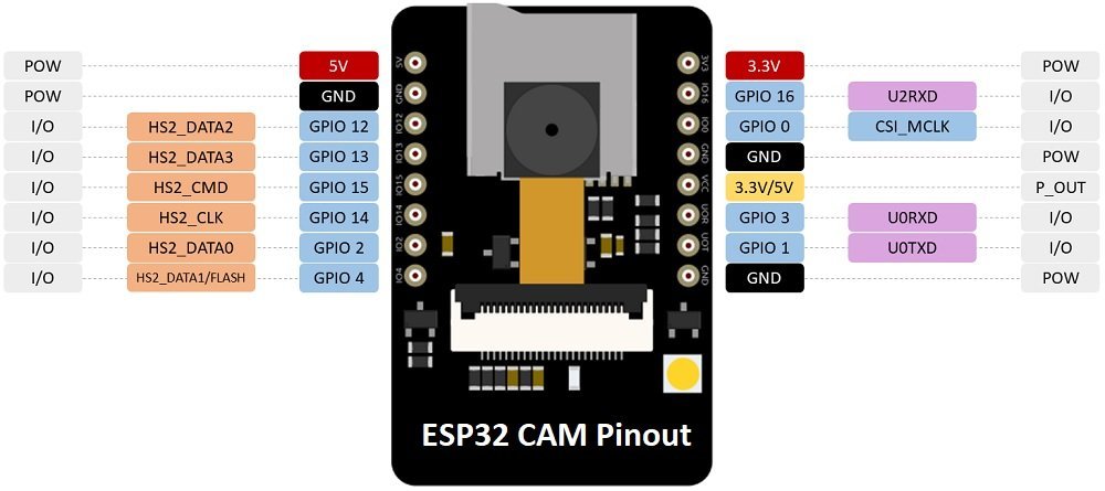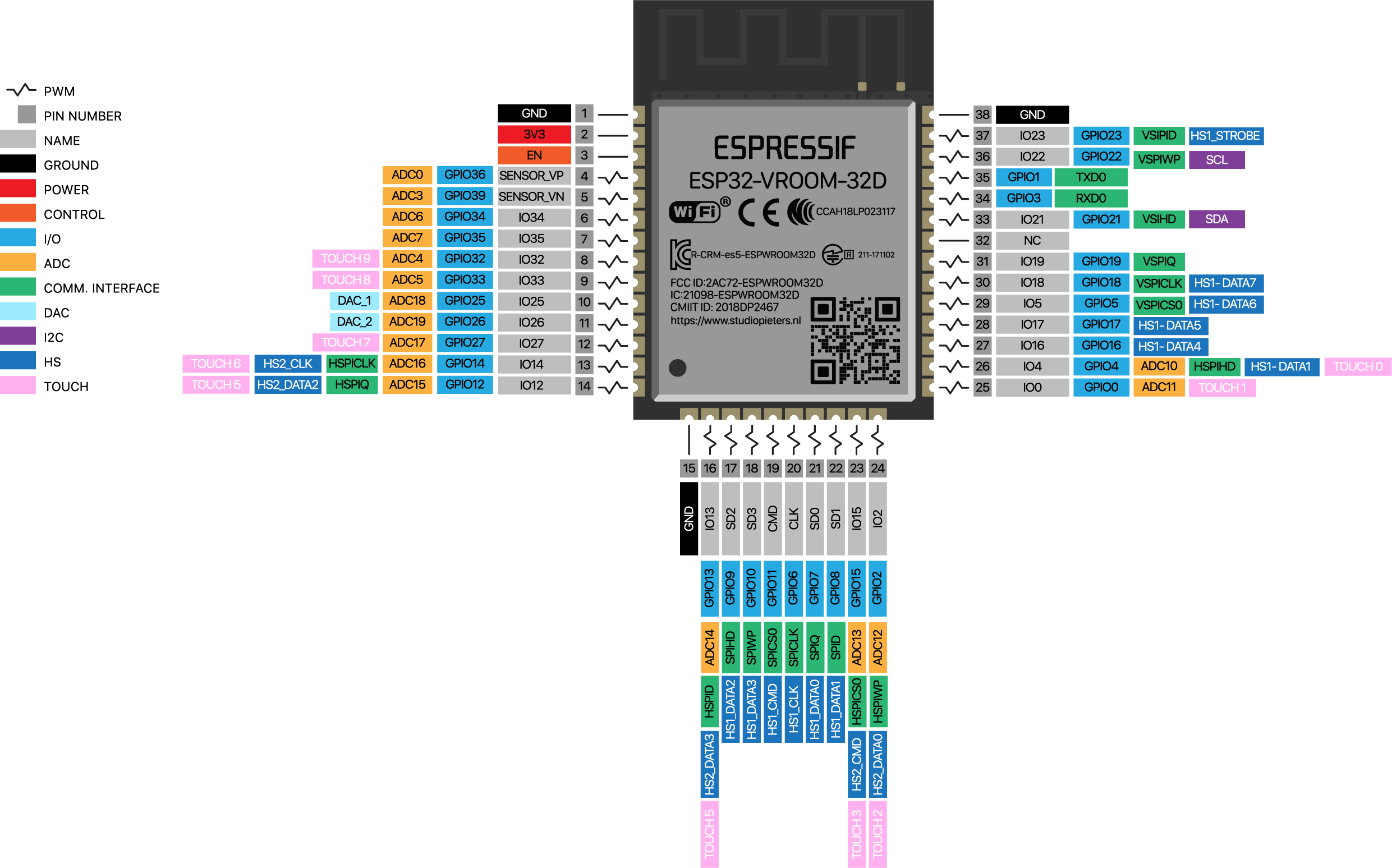

Has an internal pull-up, so unconnected = High = normal output.įor more information, consult the ESP32 Datasheet, section “Strapping Pins”. If driven Low, silences boot messages printed by the ROM bootloader. May prevent flashing and/or booting if 3.3V flash is used and this pin is pulled high, causing the flash to brownout. Has internal pull-down, so unconnected = Low = 3.3V. If driven High, flash voltage (VDD_SDIO) is 1.8V not default 3.3V. Other Pins Īs well as GPIO0 and GPIO2, the following pins influence the serial bootloader mode: In normal boot mode (GPIO0 high), GPIO2 is ignored. GPIO2 must also be either left unconnected/floating, or driven Low, in order to enter the serial bootloader.

Many boards use a button marked “Flash” (or “BOOT” on some Espressif development boards) that pulls GPIO0 low when pressed. GPIO0 has an internal pullup resistor, so if it is left unconnected then it will pull high. Otherwise it will run the program in flash. The ESP32 will enter the serial bootloader when GPIO0 is held low on reset. For other configurations or custom hardware, you will need to check the orientation of some “strapping pins” to get the correct boot mode: Select Bootloader Mode GPIO0 On many development boards with built-in USB/Serial, esptool.py can automatically reset the board into bootloader mode. Information about ESP32 strapping pins can also be found in the ESP32 Datasheet, section “Strapping Pins”. If you want to connect a switch button to enter the boot mode, this has to be a strong pull-down. The ESP32 has a 45k ohm internal pull-up/pull-down resistor at GPIO0 (and other pins).


 0 kommentar(er)
